networking and communications (I2C Bus)
This weeks assignment is to build a network of devices with at least 2 nodes, Sound perfect for me since i have build my Out/Input Devices with I2C in mind i can use this weeks assignment to build and test the diffrent elements of the I2C bus network
Project: I2C Translator
Goal: Build an I2C Serial Bridge device for communicatoin protocol design and debugging
Files Used In this Project can be Downloaded here
Let the Dance Begin !!!
To be Honest this week did not have a lot of circuit design to it because the hello.I2C.45.bridge Board on the Assignment Page has exactly what i need but to me just making the board on the page seemed boring to me so i tride re designning thinking that i can improve upon it but as excpected nothing happedn and i ended up making the same board (It just has all i need no extras PERFECT)
Anyway Stuborn as i am i redesigned anyway
Schematic:
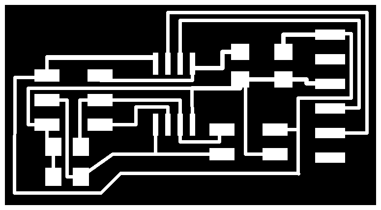
And after a bit of layout we get this a littil bit diffrent then the Original
Dose The job
And After a bit of gimp work we get a set of working Fabrication Files


And After a Milling and Cutting the board
And after Decking Out the board we get
Beuty (Dave Jones from the EEVBLOG)
Now Comes the test of truth: avrdude -c usbtiny -P usb -p t44
And after 2 Errors Not from the board not from wiring not from the software but from the test itself T45 not T44 (*insert FACE PALM SLAP Here*) we get another Sucsess
now for the Programming
Reading up on the attiny MCU they do support I2C but the arduino IDE is still not100% in support of these New Cores so the awsome guys at the HIGH Low Tech Websit Refranced the TinyWire Lib and after a bit of reading i downloaded the libraryis but they where not compiling in the code i wrote because of the following :
- SoftwareSerial arduino Lib requires the MCU to run at at least 8MHz
- The TinyWire Is by defult set to run at 1MHz
- The code was to big for MCU Flash Memory
And After Addresing theses issues i was able to compile and upload the code to the mcu
the I2C Bridge Board "Master" code at this stage bascily takes data from the Serial port and forwards it to the I2C bus thus esablition un dirctional communication
While The Servo Driver Board "Slave" (From The Output Device Assignment) Runs Firmware that allowes it to recive data from the I2C Bus and when get in the byte 0x01 it goes through a basic servo sweep
And Here is Every thing wired and working EPIC SUCSESS
That all i could get done this week, Next Step to allow the servo driver to controll 6 Servo Motors using kinimatic data genrated by the CPU and sent via I2C
Awesome See you Next Week
